Extending Wireless Charging to Higher Power Applications Circuit Diagram This document describes the design and construction of a wireless charging system using inductive coupling. The system works by using an oscillation circuit to convert DC energy to AC energy and transmit a magnetic field through a transmitter coil. This magnetic field induces a current in a receiver coil. The transmitter and receiver coils are designed based on calculations using Ampere's law Our Laser Cut Files Store: https://x-creation.com/store/ How to make Simple Wireless Power Bank charger*List Of Materials with Buy Link:https://x-creation.
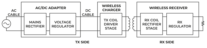
Wireless charging system overview. Wireless charging systems have three elements: a power adapter, a charging cable and a wireless charging pad. AC voltage from the power line is converted into DC voltage by the power adapter. The charging cable provides the adapter power to the charging pad, which wirelessly transmits the power to the mobile A wireless rechargeable power bank. Simply put, the wireless power bank establishes a connection without a USB cable. But the device has to be wireless charging compatible; otherwise, it won't work. 3. Standard Power Banks. These are the most prevalent or regular power banks in the market. You can get one online or at any of your local stores
How to design wireless charging systems for safe, reliable operation Circuit Diagram
For this Power bank, we have designed a PCB layout and schematics by using online website EasyEDA. You can find all the PCB layouts, schematics and Gerber files in the description below. In this system we have used a charging circuit to charge battery of power bank (18650 Lithium cell) and another circuit on the same board to charge the mobile
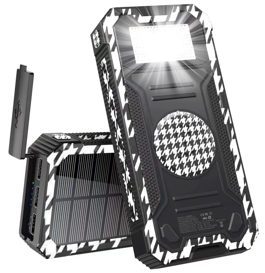
This document describes a project to design a solar powered wireless charger. The charger will use a solar panel to convert sunlight into electricity, which will charge a battery. A wireless charging circuit will then allow devices to charge without cables by using inductive coupling between the charger and device. The project aims to create a functional and efficient portable power source

Solar Power Bank With Wireless Charger Circuit Diagram
To learn more about circuit protection, sensing, and power management solutions for wireless EV charging design, download the guide, Supercharged Solutions for EV Charging Stations, courtesy of Littelfuse, Inc. Contact Littelfuse for more information on making your wireless charging system design safe, efficient and reliable. References: 1 L
